If skinning conditions are suboptimal, maybe it's time to think about avalanche transceiver testing.

If skinning conditions are suboptimal, maybe it’s time to think about avalanche transceiver testing.


Should you or shouldn’t you? A signal acquisition test to determine if you should replace your transceiver.


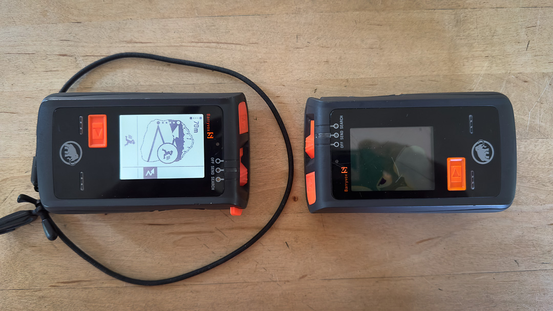
In our attempt to be concise and straightforward, this post will focus on a single aspect of testing your avalanche transceiver: signal acquisition. Signal acquisition is a more technical way of describing the distance from which the searching transceiver first picks up a signal from the sending device. For example, using the Barryvox S, in a best-case scenario, the manufacturer claims a digital receiving range of 70m.

Here, I’m testing a few things when eyeing signal acquisition. I want a receiving range close to a best-case scenario. Further, I want consistent readings, so I’ll run the test a few times for validity.

The testing protocols were/are simple. I found a somewhat electromagnetically quiet space. I traveled to a local forest away from potential electromagnetic interference. No power lines were nearby. I left my phone in the car and was not wearing a watch or any other personal electronic devices. I used two Barryvox S transceivers. One has a cracked screen and is used as my test “send” transceiver during practice—the other Barryvox S is fully functional and is being tested for signal acquisition.


Some small electronics dissection on the broken-screen transceiver. Note, one of three antennas lying horizontally at the bottom of the unit.

Some small electronics dissection on the broken-screen transceiver. Note, one of three antennas lying horizontally at the bottom of the unit.


Another perspective with the X, Y, and smaller Z antennas exposed. Do not void your warranty or otherwise ruin a functional transceiver. This unit has a broken screen, and provides a useful send/transmit beacon when practicing with the safety tools.

Another perspective with the X, Y, and smaller Z antennas exposed. Do not void your warranty or otherwise ruin a functional transceiver. This unit has a broken screen, and provides a useful send/transmit beacon when practicing with the safety tools.

Some General Tech Background 

Newer transceivers, referred to as digital, have three antennas. The antennas assist with signal transmission and acquisition. For our purposes, we are mainly concerned with signal acquisition, or the ability of the test transceiver to acquire the signal from the sending transceiver. But for the sake of science, let’s go a nano-meter deeper. Each antenna transmits in a signal plane. So, most brand’s antennas are oriented perpendicular to one another: they transmit in either the X and Y planes. During a course search, the receiving transceiver can triangulate off the X or Y flux lines and provide a general direction and distance to the transmitting transceiver. A third antenna, call it “Z,” is oriented vertically. The Z signal comes into play as I close on the send signal/victim.

The best-case scenario involves the antennas in the sending and searching transceivers aligned or oriented the same way. It follows that depending on how the sending transceiver is oriented, there may be some variability in signal acquisition. I kept the orientation of my search unit consistent (facing forward and screen up in my hand/palm) while orienting the send unit in three discrete positions, referred to as positions A, B, and C. I ran each scenario two times. 

Send transceiver (on right) in orientation A for the signal acquisition test.

Send transceiver (on right) in orientation A for the signal acquisition test.

Send transceiver (on right) in orientation B for the signal acquisition test.

Send transceiver (on right) in orientation B for the signal acquisition test.

Send transceiver (on right) in orientation C for the signal acquisition test.

Send transceiver (on right) in orientation C for the signal acquisition test.

Testing

  • Find a space with little, if any, electromagnetic interference. We are trying to approximate a backcountry snow slope. 
  • Set the transmitting (or send) transceiver down in the A orientation. 
  • Walk roughly 100m from the send transceiver. 
  • Turn the search beacon on, then switch to search mode. Hold the unit ~50cm in front of you, point right at the send beacon, and walk towards that unit. 
  • Note the initial signal acquisition from the sending unit—you’ll hear a beep; the distance and direction will be displayed on the screen.
  • Turn the search unit off, then on again. 
  • Repeat the process a second time, cataloging the signal acquisition. Some variability will exist—expect the signal acquisition distance to vary by +/- 5m between trials. 
  • Now, repeat with the send unit in orientations B and C. B and C offer less optimal antenna orientations relative to the search unit in your hand. The signal acquisition distances should decrease accordingly.  


Results

My test transceiver is a five-year-old unit that has been treated well. I remove batteries during the off-season and try not to trash it (read, no big impacts). Results were as follows with trial 1 & 2 included for the A, B, and C orientations:

  • I found an initial signal acquisition at 63m and 59m in send orientation A.
  • I found an initial signal acquisition at 48m and 51m in send orientation B.
  • I found an initial signal acquisition at 38m and 32m in send orientation C.

Although my go-to transceiver will be out of warranty soon, it passes the signal acquisition test. If your results seem off (as in way below the manufacturer’s specs for digital signal acquisition), or the readings are inconsistent, check in with your manufacturer for next steps. You might need to send the unit in for a thorough diagnostics test.